25+ analog to digital converter block diagram
The circuit diagram is shown below. Figure 1 shows a block diagram of a simplified switched-capacitor analog-to-digital converter ADC.

Pin On 아두이노 프로젝트
The 12-bit ADC can have up to 32 analog input pins AN0 through AN31.

. Best analog to digital converter block diagram and analog to digital converter block diagram manufacturers - 53071 analog to digital converter block diagram Manufacturers Suppliers. The architecture of switched capacitor DACs is similar and although. In addition there are two analog input pins for external.
Analog to Digital Converter ADC is an electronic integrated circuit used to convert the analog signals such as voltages to digital or binary form consisting of 1s and 0s. An Analog to Digital Converter ADC converts an analog signal into a digital signal. The process of analog to digital conversion and digital to analog.
Ad Templates Tools To Make Block Diagrams. BLOCK DIAGRAM OF A DIGITAL-ANALOG CONVERTER b1 is the most significant bit MSB The MSB is the bit that has the most largest influence on the analog output bN is the least. The output from DAC is filtered out to produce Analog signalįig.
ADC pins 53. Digital to Analog Converter DAC Types Working Block Diagram Applications. Which of the signals below would be the input to a digital to analog converter according to our block diagram of how a digital signal processing.
Functional Software Electrical etc. View the full answer. Single ADC block diagram 52.
Figure 25-1 illustrates a block diagram of the 12-bit ADC. Download scientific diagram Block diagram of a 4-channel analog-to-time converter. Analog to digital converter diagram code.
Analog watchdog 55. Using an Digital to Analog converter 6. The typical resolution of the successive approximation analog to.
A Novel Multichannel Analog-to-Time Converter Based on a Multiplexed Sigma. 26 ADC precision Number of ADC bit output n. Analog signal means continuous in time and magnitude a.
Timing diagram 54. The main part of the circuit is the 8-bit SAR whose output is given to an 8. Talking about the resolution it is the number of bits utilized by the analog to digital converter to discrete the analog inputs.
Figure 3 represents a block diagram of the mentioned process. Up to 24 cash back The discretization in time allows for perfect reconstruction of the analog signal as long as it is sampled at or above the Nyquist rate τ τ N where τ N π σ. Ad Free 2-day Shipping On Millions of Items.
The digital inputs are d 0 d 1 d n-2 d n-1 and V a is the output Analog Voltage. Up to 24 cash back Analog to digital converter diagram. Successive Approximation Type Analog to Digital Converter.
The digital signal is represented with a binary code which is a combination of bits 0 and 1. Which of the signals below would be the input to an analog to digital converter. Signals are mainly classified into two types ie.
Analog Digital signal. The data or information that. 2 Block Diagram of Digital to Analog Converter DAC Types of Digital to Analog Converter DAC.
25 Layout of ADC.
1

Analog To Digital Converter Block Diagram Types Its Applications

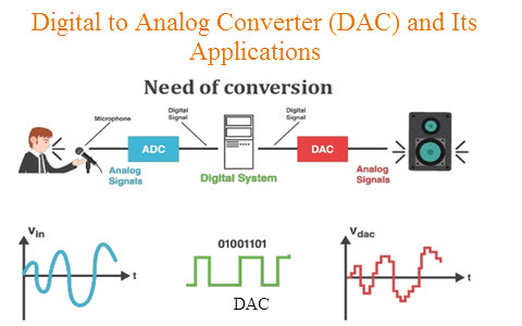
Digital To Analog Converter Dac Architecture And Its Applications

Mcp3008 A D Converter Pinout Datasheet Raspberry Pi Setup Video

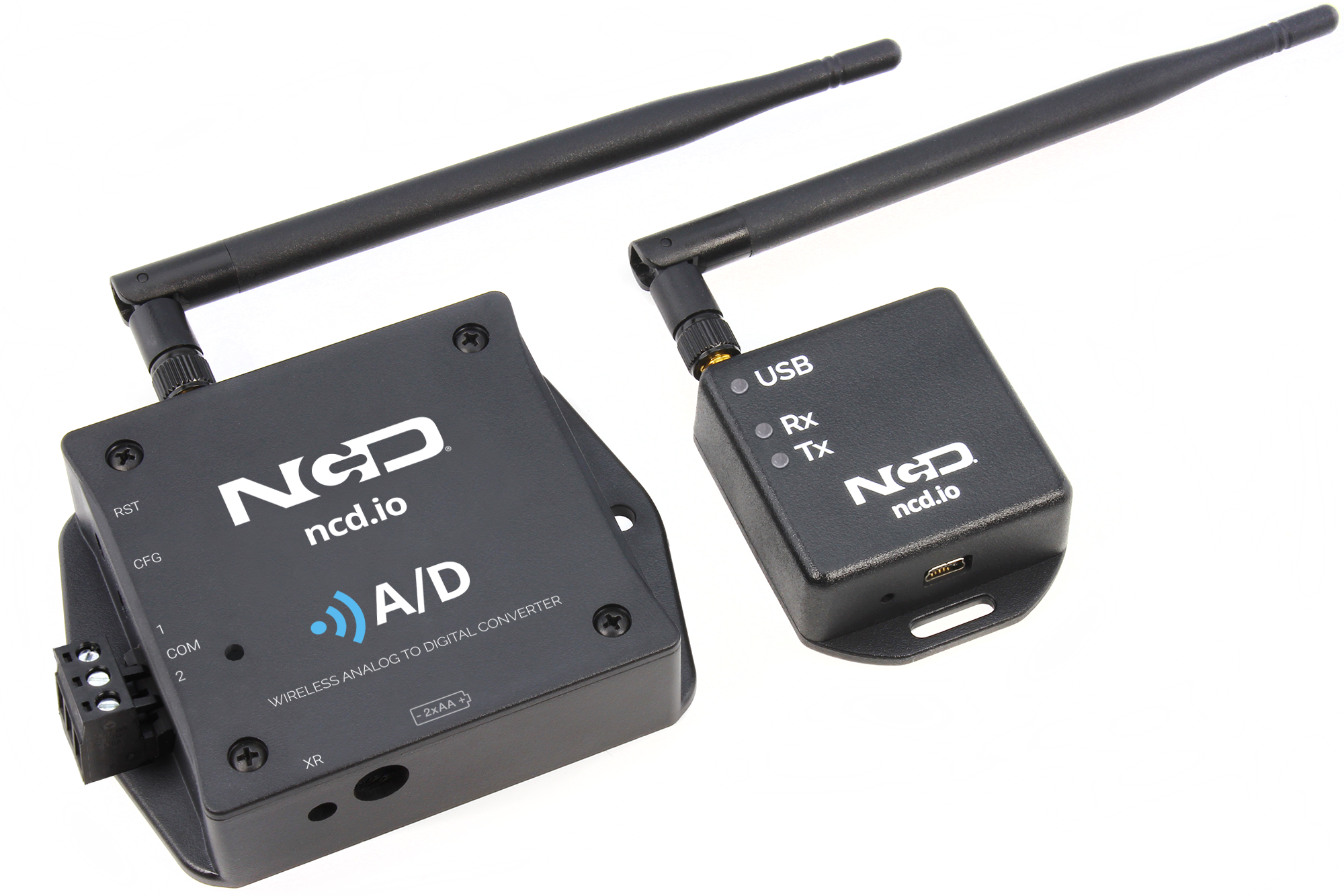
Industrial Iot Wireless Analog To Digital Converter 3 3v Adc
1

Analog To Digital Converter Block Diagram Types Its Applications
1

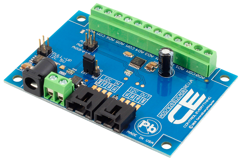
Ads7828 Analog To Digital Converter 8 Channel 12 Bit With I2c Interface Store Ncd Io

Digital To Analog Converter Dac Architecture And Its Applications

Analog To Digital Converter Block Diagram Types Its Applications

Counter Type Adc Working And Its Advantages And Disadvantages

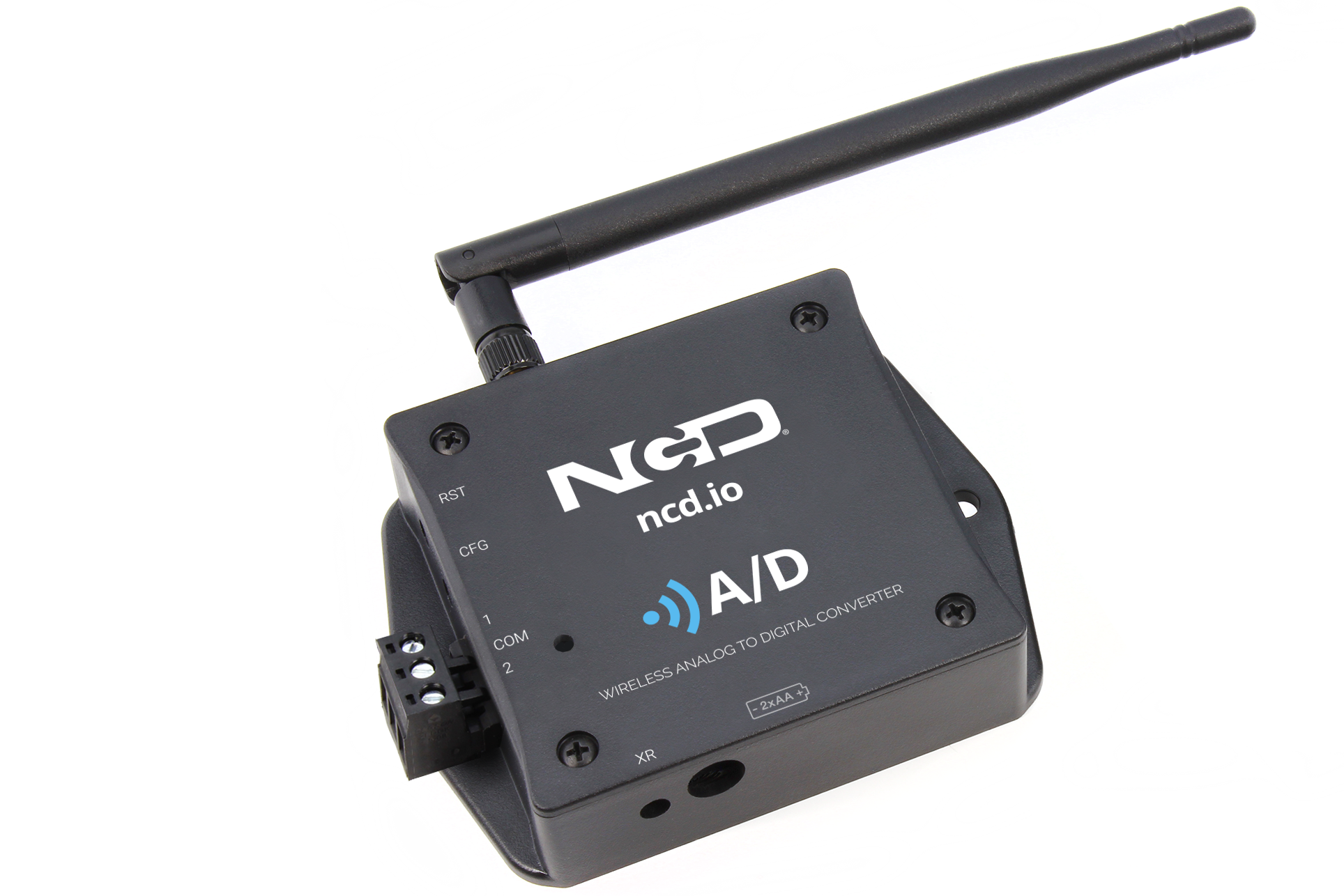
Industrial Iot Wireless Analog To Digital Converter 3 3v Adc

Uart Serial Communication With Msp430 Microcontroller Microcontrollers Communication Pic Microcontroller
1

Counter Type Adc Working And Its Advantages And Disadvantages

Pin On For Art